Electronics
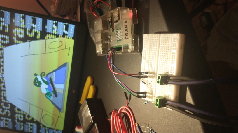
The platform uses a simple Arduino circuit to send input to the game. This document explains how to create the circuit shown above and load the necessary program onto it. The above image shows a Raspberry Pi in place of the Arduino, but the circuit is identical.
Circuit
Four input pins on the Arduino need to be connected to the game's four input pads, with a 4.7k resistor in each connection.
- Add the screw terminals the breadboard, making sure there are four terminals total, with each pin in its own row on the breadboard. In the image above, two components are used, each containing two terminals.
- Connect a 4.7k ohm resistor to each terminal pin by placing it in the same row as the terminal.
- Finally, connect Arduino pins 2, 3, 4, and 5 to the breadboard using jumper wires, one to each row that ends in a screw terminal (refer to the colored wires in the image above).
Loading the program
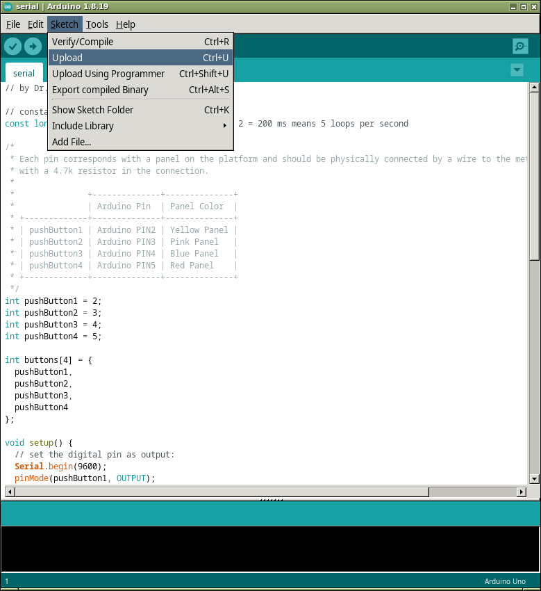
Download the Arduino IDE and connect it to the Arduino. Make sure the Arduino is connected in Tools -> Port. Open the file serial/serial.ino from the Scrapeboard code repository into the IDE. Load the program into the Arduino using Sketch -> Upload.
Testing the circuit
Launch the game without any flags to indicate Arduino mode. Serial data being output by the Arduino will be read over USB. Run the following from the root of the Scrapeboard code repository in the terminal to launch the game (for example, from Powershell on Windows, or Terminal on OS X).
./OPEN-GAME
Each screw terminal corresponds to one of the four metal plates on the platform. Input is sent to the game by connecting any two metal plates using another piece of metal as a conductor, for example, the metal on the underside of the board. For now, use a jumper wire to test the connections between screw terminals. Insert one end of the wire into any terminal, and the other end into any other. The lizard should appear on screen.
Nano
The circuit can be mounted directly to the underside of the platform with the help of a micro Arduino. This upgrade allows the platform to connect to the computer with just a USB cable. While this circuit will not be able to connect directly to Raspberry Pi pin headers, it can still be connected to a Pi using the USB port.
Supplies
- Arduino-compatible mini microcontroller (for example, Pro Micro, Nano, or ESP)
- PCB prototype board
- Pin headers
- 4.7k resistors
- 5mm screw terminals
- Soldering iron and solder
- Sheathed wire and wire strippers (optional)
Instructions
- Solder one row of headers into the side of the microcontroller that contains digital pins 2 through 8. Soldering the other side is optional. The best way to solder the headers is to stick them into a breadboard and lower the microcontroller onto them before soldering.
- Insert the row with digital pins 2 through 8 into the PCB prototype board and solder the pins to the underside of the board. It should be centered and inserted long ways across the second row from the center, row D, from column 2 to 16.
- Connect eight total screw terminals together and insert them into the opposite side of the board, row A, from column 2 to 16. Solder the pins to the underside of the board.
- Insert the four resistors, so they each connect from one of digital pins 2, 3, 4, and 5 to a screw terminal. The connections are F12-E16, F11-E14, F10-C12, F9-C10. Solder the pins to the underside of the board.
- Pins 6, 7, and 8 can also be connected to screw terminals. These pins are not in use yet, but a future update is planned to connect an RGB light strip.
| ⬅ Previous Page | Next Page ➡ |
|---|---|
| Software | Platform |